
Page 17 - Acoustic Fluid Level Measurements
P. 17
Fluid Level Measurement Applications for Gas Lift Wells 10-1
Petroleum Extension-The University of Texas at Austin
10
Fluid Level Measurement Applications for Gas Lift Wells
In this chapter:
• Unloading status and operating valve identification
• Determining static and producing BHP
• Pressure distribution at steady flowing conditions
• Pressure distribution at shut-in conditions
• Recommended equipment and procedures
• Example acoustic records
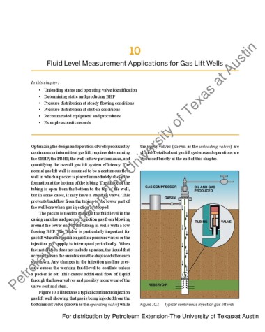
Optimizing the design and operation of wells produced by the upper valves (known as the unloading valves) are
continuous or intermittent gas lift, requires determining closed. Details about gas lift systems and operations are
the SBHP, the PBHP, the well inflow performance, and discussed briefly at the end of this chapter.
quantifying the overall gas lift system efficiency. The
normal gas lift well is assumed to be a continuous flow
well in which a packer is placed immediately above the
formation at the bottom of the tubing. The inside of the
tubing is open from the bottom to the top of the well, GAS COMPRESSOR OIL AND GAS
PRODUCED
but in some cases, it may have a standing valve. This GAS IN
prevents backflow from the tubing to the lower part of
the wellbore when gas injection is stopped.
The packer is used to stabilize the fluid level in the
casing annulus and prevent injection gas from blowing TUBING VALVE
around the lower end of the tubing in wells with a low
flowing BHP. The packer is particularly important for
gas lift when the injection gas line pressure varies or the
injection gas supply is interrupted periodically. When
the installation does not include a packer, the liquid that
accumulates in the annulus must be displaced after each
shutdown. Any changes in the injection gas line pres-
sure causes the working fluid level to oscillate unless
a packer is set. This causes additional flow of liquid
through the lower valves and possibly more wear of the
valve seat and stem. RESERVOIR
Figure 10.1 illustrates a typical continuous injection
gas lift well showing that gas is being injected from the
bottommost valve (known as the operating valve) while Figure 10.1 Typical continuous injection gas lift well
For distribution by Petroleum Extension-The University of Texas at Austin
10-1